KANOPY & Crafting electrochemistry for lives…

Ir Compensation: Definition And Methods Of Evaluation

Kanopy Techno Solutions

IR compensation: Definition and methods of evaluation

Posted on June 15, 2021, 5:19 p.m. by electrochemical.expert@kanopytech.com


The current-voltage relationship of an electrochemical investigation contains essential information of the electrode-electrolyte interface. However, the accuracy of data always bother the electrochemists for the correct evaluation of interfacial properties. While the accurate measurement of current is reasonably straightforward, measuring potential across the interface is impossible as the potential measuring probe in the electrolyte can not measure the potential at the solution side. Therefore, the potential difference is measured across the working electrode and reference electrode in a typical three-electrode setup. Since these electrodes are at a finite distance to each other in the electrolyte solution, an additional potential drop is observable due to the current flowing through the electrolyte with non-zero resistance. This drop in potential is known as IR drop, the effect of which must be compensated in electrochemical measurements.

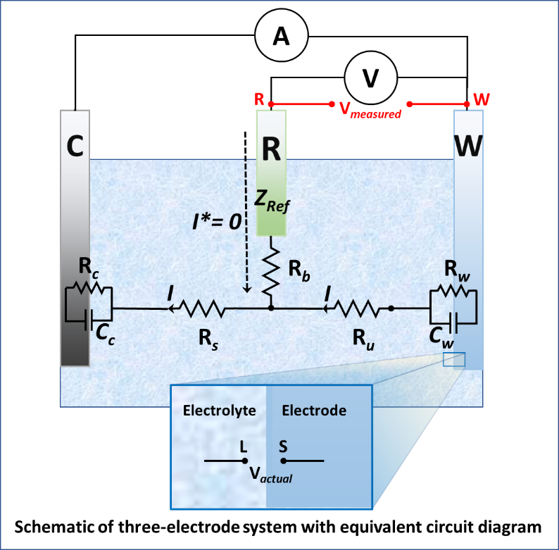
Consider a typical three-electrode system that consists of an equipotential working electrode and ideally polarizable reference electrode as shown in the schematic. The equivalent circuit associated with the system gives a deep insight into electronic current flow through the circuit. Let assume that the currents I and Iare flowing through the working and reference electrodes, respectively. Since the reference electrode is an ideally polarizable electrode, no current will pass through it, and hence, the current I  will flow through the counter electrode and be measured by the workstation. The notations in the schematic are defined below:

Rw = Charge transfer resistance across the interface of the working electrode

Cw = Double-layer capacitance across the interface of the working electrode

Ru = Uncompensated resistance

Rb = Salt bridge resistance

ZRef = Impedance of reference electrode

RS = Solution resistance

RC = Charge transfer resistance across the interface of the counter electrode

CC = Double-layer capacitance across the interface of counter electrode


We know that all the workstations can control/measure the potential between point R and W. Therefore, it can be written as:

Vmeasured=VW-VR                    (1)

Since the actual potential difference should be calculated at the electrode-electrolyte interface, we can write the potential difference at the interface as

Vactual=Vs-Vl                              (2)

Where Vs and Vl  are the potentials of a solid electrode and liquid electrolyte at the interface. Since the working electrode is an equipotential surface,  Vs  will be equal to Vw. Therefore equation 2 can be written as

Vactual=VW-Vl                            (3)

Applying Kirchhoff’s second law between point L and R:

Vl-VR= I.Ru-I*.Rb-I*.ZRef+VOC                             (4)

where, VOC  is the Fermi level difference of working and reference electrodes. Therefore,

Vl-VR= I.Ru+VOC                   (5)

Rearranging equation 5 results into

Vl= VR+I.Ru+VOC                   (6)

Combining equation 3 and 6 results into

Vactual=VW-VR-I.Ru-VOC              (7)         

or

Vactual=Vmeasured-I.Ru-VOC           (8)         

At the right-hand side of the equation, all the parameters are directly measurable except Ru. Therefore, Vactual can be calculated if we know Ru. The easiest way to calculate the  Vactual is by elimination of potential drop due to uncompensated resistance. This can be achieved either by increasing the conductivity of electrolyte (through the addition of supporting electrolyte) or by decreasing the distance between reference and the working electrode (typically through a lugging capillary). However, these methods can result in erroneous measurements. For example, the use of supporting electrolytes can disturb the double layer. Though supporting electrolytes do not participate in the electrochemical reaction, they may also affect the adsorption/desorption kinetics of electroactive species. Therefore, IR compensation through experimental methods is a better tactic to deal with the problem. These methods are described below:

  1. Measurement through AC technique: In this technique, a variable frequency signal is passed through the cell, typically using the EIS technique. The low-frequency signal accounts for the potential drop across both Ru and RC whereas the high-frequency signal accounts for potential drop only across Ru. The variation of resistance with frequency (Bode plot) is plotted, which determine the Ru.
  2. Measurement through DC technique: In this technique, a transient current interrupt is applied for the duration of 10µs-30ms across the electrochemical cell. Simultaneously, The voltage ( Vmeasured ) is recorded just before and just after the current interruption. During such a short span, an instantaneous voltage drops ( V u ) is observable across Ru which accounts for the IR compensation. The Vactual  is calculated by subtracting V u  from Vmeasured . Afterward, a gradual potential drop is observed across Rf  due to slow discharge of Cf  which is observable only if we record the signal for a longer time; however, not of our interest. Unlike the previous method, this method provides a dynamic IR correction which means that the system automatically compensates the changes for varying  Ru.

Share this post!
Thank you for visiting www.kanopytech.com. We have tried to optimize your experience while on the site, but we noticed that you are using an older version of a web browser. We would like to let you know that some features on the site may not be available or may not work as nicely as they would on a newer browser version. If you would like to take full advantage of the site, please update your web browser to help improve your experience while browsing www.kanopytech.com.